


Assembling a liteon probe pictorial
Clicks: 103638
Author:
UPDATE --- This tutorial is only useful for 74850C LiteOn drives. For 83850C v1 drives, no extra hardware is needed, only a SATA connection. For 83850C v2 and 93450C drives you need to do the MRA hack, which involves cutting and soldering traces on the drives board. The MRA hack can be used on 74850C drives also (and has the added advantage of dumping the full firmware, not just the key and identity info) ---
As I was assembling a probe today, I thought i would take some pictures and show you all an easy, neat way to assemble these things. I have seen a lot of messy builds, its no surprise some of them don't work.
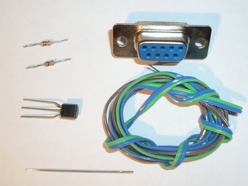
First gather all your components,
1x 10K resistor (marked brown black orange gold)
1x 1k resistor (marked brown black red gold)
1x NPN signal transistor (eg: BC546/7/8/9 BC337/8 C945 2N2222 see main tutorial for pinouts)
1x DB9 female serial plug
some lengths of wire
a needle for the probe / a multimeter probe / sharpen the leg of a resistor
Tools:
soldering iron and damp sponge (15 Watt or adjustable heat setting)
solder (0.5mm flux cored is good)
some electrical tape / hot glue / shrink-wrap tubes to tidy everything up to your taste.
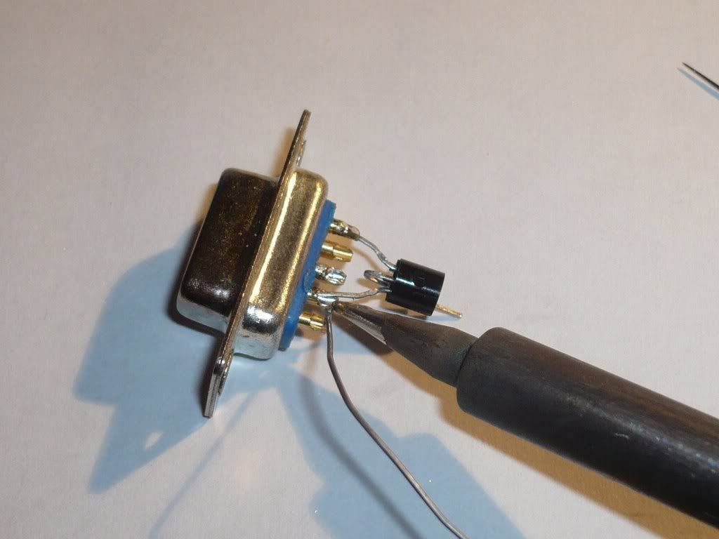
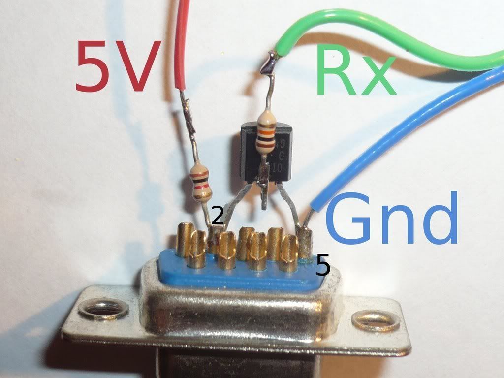
The transistor used here is a BC549 which shares the same CBE pinout as a BC547
Trim the transistor leads and bend up the base lead, then fit the transistor so that the collector sits in pin 2 and the emitter sits in pin 5

When soldering the transistor, heat up the joint while applying solder, don't leave the iron on the joint for more than a few seconds.
Solder the 1K resistor to the joint at pin 2 and the 10k resistor to the base lead. when soldering the 10k it is best to 'tin' both leads first to get some solder on the leads.
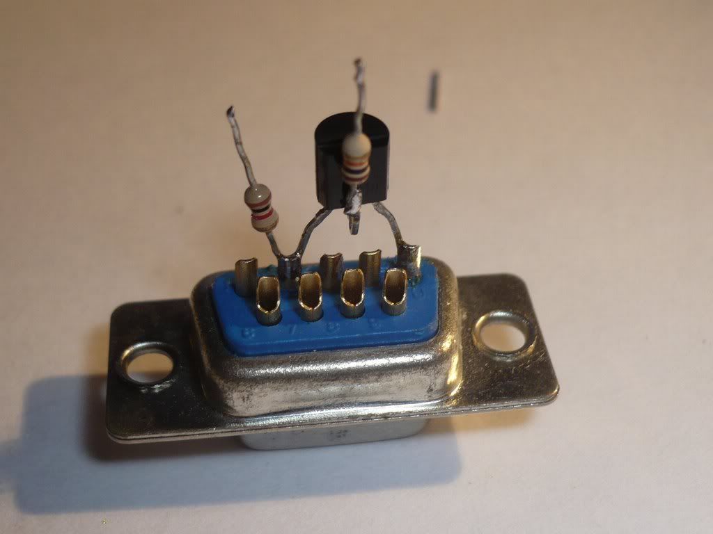
Tin the ends of three wires by heating the wire while applying solder
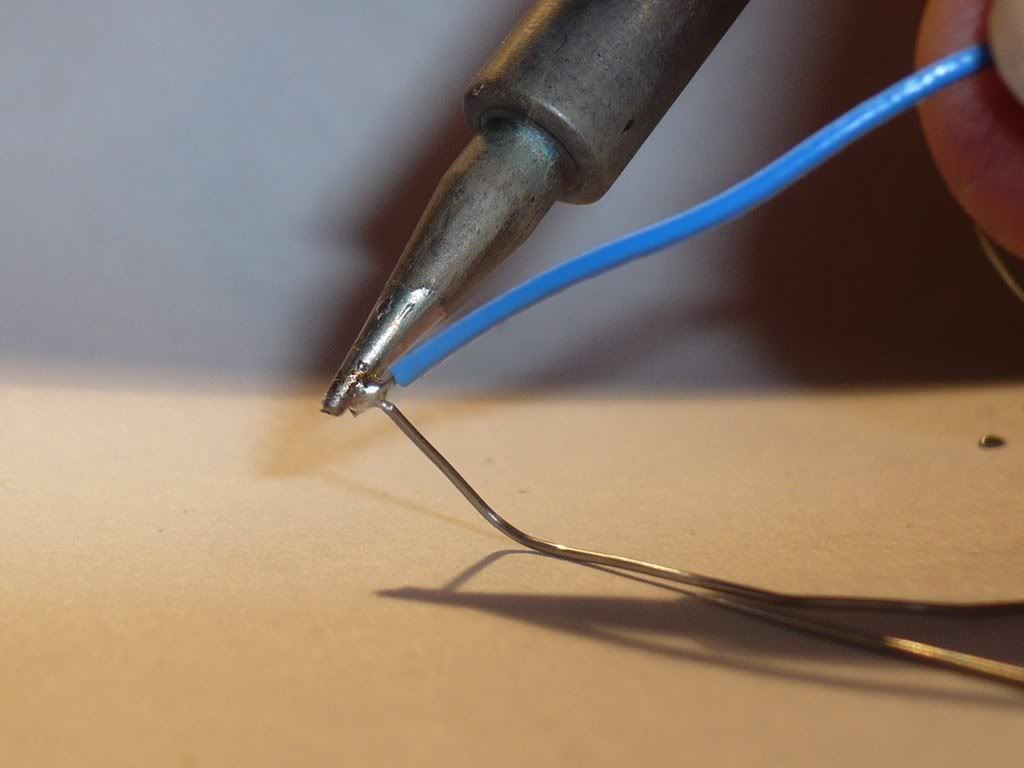
Then solder the wires to their respective joints as shown.
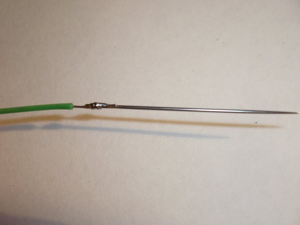
Get a sewing needle and put the other end of the probe wire through the eye, wrapping the wire around the needle, then solder this for a good connection.
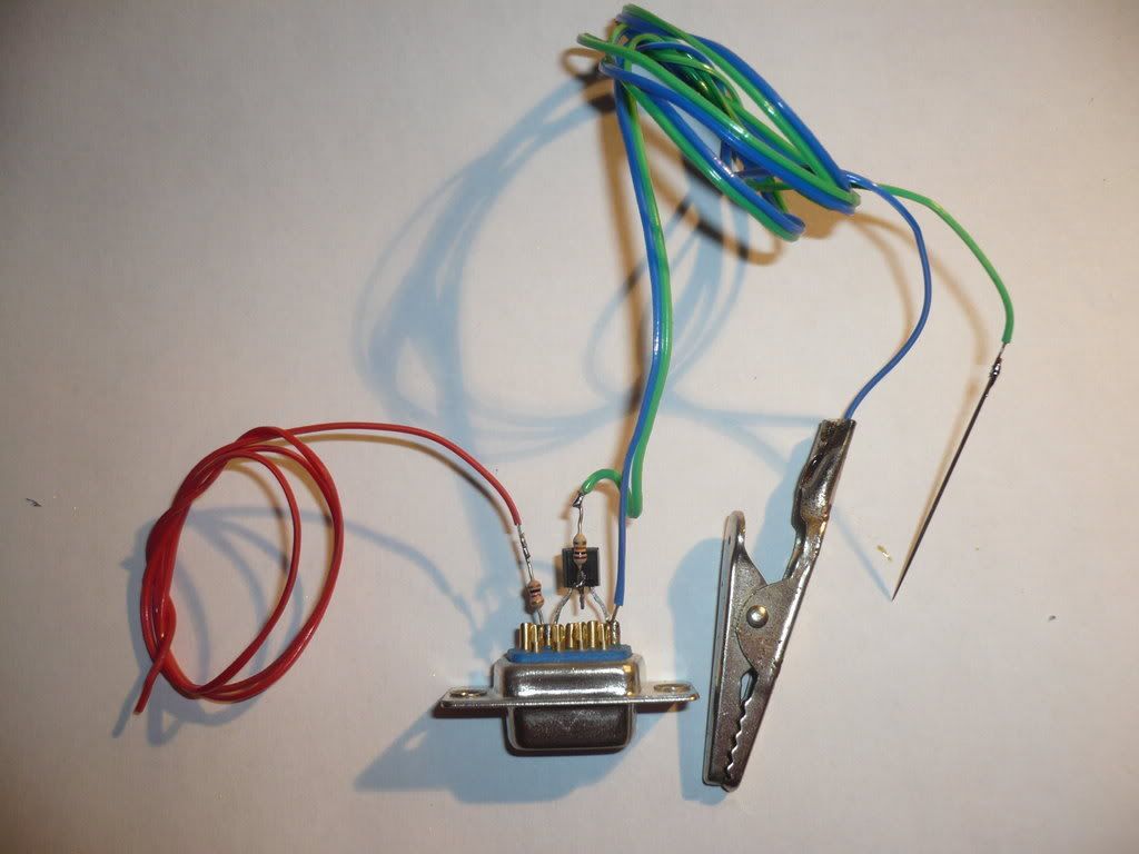
If you have a crocodile clip, solder this to the ground wire for easy grounding of the drive.
To test the setup I plugged it in to a serial port (using a cable) and used three 1.5V cells to power the circuit with about 5V. I then rubbed the probe against the first cell to test the circuit with 1.5V.

The output of hyperterminal will look something like this... totally random.

Once you have confirmed the circuit is working, you should insulate the bare wires to prevent shorting. Especially make sure the 5V joint at the 1K resistor (red wire in my circuit) is insulated, if this wire shorts out it can damage your circuit and/or computer and/or drive.
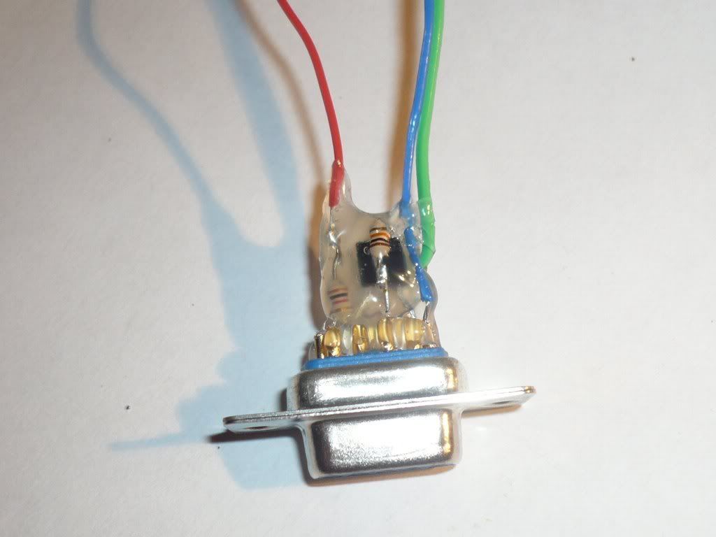
Hot glue is great.
have fun :)
comment in the forums.
Notice: The Tutorials have been done many times and were often successfull, however we cannot guarantee the success and so dont take any responsibility for any damages that might be caused by it, you do it on your own risk!!!